
Any Transport over MPLS
Any Transport over MPLS or AToM in short is a method of encapsulating Layer 2 packets inside MPLS. Much like it’s cousin L2TPv3 it has the ability to transport any Layer 2 encapsulating such as PPP, Ethernet etc. AToM enables Service Providers to supply Layer 2 connectivity between customer sites with existing data link layer networks. The original RFC AKA “Draft Martini” 4906 after the author. With AToM it’s possible to take an existing MPLS infrastructure and deliver end to end Layer 2 connectivity.
Supported Layer 2 encapsulated payloads
- Frame Relay
- Ethernet
- 802.1q VLAN Tagging
- IEEE 802.1QinQ and QinAny VLAN
- HDLC
- PPP
- ATM
- RFC – ( Draft Martini ) – 4906
Requirements
- Cisco Express Forwarding or CEF must be enabled
- An IGP such as OSPF, IS-IS, or simply BGP depending on the design
- The source of the MPLS / LDP tunnel should originate from a loopback interface
- The destination of the MPLS / LDP tunnel should terminate on a loopback
- The loopback interfaces must have unicast reachability
- Optional if not already enabled would be to turn on CDP
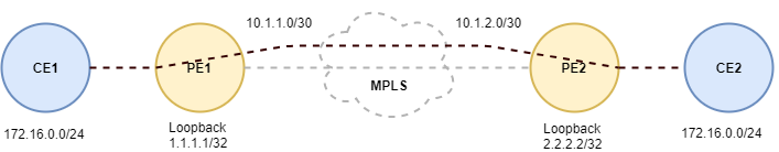
It’s not actually depicted in the above diagram, but there is a P router that exist within the MPLS, cloud so lets start off by configuring all three. I’m also going to use OSPF as my IGP in order to bring up the LDP control plane.
PE1#configure terminal
PE1(config)#interface interface ethernet2/0
PE1(config-if)#no shutdown
PE1(config-if)#ip address 10.1.1.2 255.255.255.252
PE1(config-if)#router ospf 1
PE1(config-router)#router-id 1.1.1.1
PE1(config-router)#network 0.0.0.0 255.255.255.255
PE1(config-router)#mpls ldp autoconfig
PE1(config-router)#exit
PE1(config)#
Next lets do the same on router PE2.
PE2#configure terminal
PE2(config)#interface ethernet2/0
PE2(config)#no shutdown
PE2(config-if)#ip address 10.1.2.2 255.255.255.252
PE2(config-if)#router ospf 1
PE2(config-router)#router-id 2.2.2.2
PE2(config-router)#network 0.0.0.0 255.255.255.255
PE2(config-router)#mpls ldp autoconfig
PE2(config-router)#exit
PE2(config)#
The next thing we need to do is bring up the loopback interfaces on Provider Edge router PE1, and PE2 AToM tunnel termination. I’m also going to be running the OSPF process along with the LDP process on both of the loopback interfaces.
PE1(config)#interface loopback0
PE1(config-if)#ip address 1.1.1.1 255.255.255.255
PE1(config-if)#exit
PE1(config)#
Now lets do the same thing on router PE2, so we can run the OSPF process along with LDP on the interface.
PE2(config)#interface loopback0
PE2(config-if)#ip address 2.2.2.2 255.255.255.255
PE2(config-if)#exit
PE2(config)#
Now lets move on to the LDP ( Label Distribution Protocol ) configuration of the P router in the cloud that’s not depicted in the above diagram.
P#configure terminal
P(config)#interface ethernet2/0
P(config-if)#no shutdown
P(config-if)#ip address 10.1.1.1 255.255.255.252
P(config-if)#interface ethernet2/1
P(config-if)#no shutdown
P(config-if)#ip address 10.1.2.1 255.255.255.252
P(config-if)#router ospf 1
P(config-router)#router-id 100.100.100.100
P(config-router)#network 0.0.0.0 255.255.255.255
P(config-router)#mpls ldp autoconfig
P(config-router)#end
P#
At this point we’re ready to move onto the actual AToM tunnel configuration on the Provider Edge routers. Lets start off with PE1, by creating the tunnel pointed at Provider Edge router PE2’s loopback interface.
PE1(config)#interface fastEthernet0/0
PE1(config-if)#no ip address
PE1(config-if)#xconnect 2.2.2.2 1 encapsulation mpls
PE1(config-if)#exit
PE1(config)#
Now that do the same thing on router PE2.
PE2(config)#interface fastEthernet0/0
PE2(config-if)#no ip address
PE2(config-if)#xconnect 1.1.1.1 1 encapsulation mpls
PE2(config-if)#exit
PE2(config)#
Last, but not least lets bring up the LAN ( 172.16.0.0/24 ) interface on router CE1, and CE2.
CE1#configure terminal
CE1(config)#interface fastEthernet0/0
CE1(config-if)#ip address 172.16.0.3 255.255.255.0
CE1(config-if)#end
CE1#
Now lets do the same thing between on router CE2.
CE2#configure terminal
CE2(config)#interface fastEthernet0/0
CE2(config-if)#ip address 172.16.0.4 255.255.255.0
CE2(config-if)#end
CE2#
At this point we should have full Layer 2 reachability between router CE1, and CE2 via AToM.
CE1#ping 172.16.0.3 source fastethernet0/0 repeat 20
Type escape sequence to abort.
Sending 5, 100-byte ICMP Echos to 172.16.0.4, timeout is 2 seconds:
Packet sent with a source address of 172.16.0.3
!!!!!!!!!!!!!!!!!!!!
Success rate is 100 percent (5/5), round-trip min/avg/max = 68/92/108 ms
CE1#
Now lets check to make sure we have full unicast ICMP reach ability from router CE2.
CE2#ping 172.16.0.4 source fastethernet0/0 repeat 20
Type escape sequence to abort.
Sending 20, 100-byte ICMP Echos to 172.16.0.4, timeout is 2 seconds:
Packet sent with a source address of 172.16.0.4
!!!!!!!!!!!!!!!!!!!!
Success rate is 100 percent (20/20), round-trip min/avg/max = 68/92/108 ms
CE2#
I hope you found this post on AToM helpful and informative. Be sure to let me know what you think by leaving suggestions, and feedback in the comments section below. You can find out more about these and other articles be checking out recent posts and archives. To learn more about me be sure to check out the About page. And as always thanks again for visiting The Packet.