
A VLAN is a switched network or virtual LAN that is logically segmented by function, groups or applications, without regard to the physical locations of the users. VLANs have the same attributes as physical LANs, but you can group end stations even if they are not physically located on the same LAN segment. Any switch port can belong to a VLAN, and unicast, broadcast, and multicast packets are forwarded and flooded only to end stations in the VLAN. In short a VLAN is a Layer 2 BROADCAST domain.
It’s difficult to talk about VLANs and Trunking without talking a little time to talk about Ethernet frames in general. It’s important to understand the formatting, and changes that take place within the Ethernet frame or header as it traverses the Ethernet network and trunks.
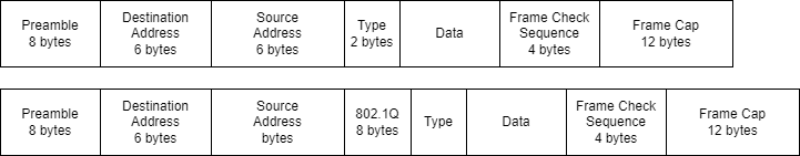
The Ethernet Header
- Preamble – Synchronization and signaling for proper clocking
- Source – The source MAC address
- Destination – The destination MAC address
- Length – The Frame size
- DSAP – Destination Service Access Point (802.2) 1 byte
- SSAP – Source Service Access Point (802.2) 1 byte
- Control – 1 or 2 byte field for connectionless or connected state
- OUI – Vendor specific 3 byte or 24 bit field
- Type – Frame type such as SNAP or DIX
- Data – Payload
- FCS – Frame Check Sequence
Newly Created VLANs
Since a VLAN is basically a virtual Switch we need two very important pieces within Control Plan in order to forward Ethernet Frames and prevent loops within the virtual Switch. So with every newly created VLAN or VLANs the following two things happen…
- A new MAC Address Table or CAM Table is created
- A new Spanning Tree instance is created
The 802.1Q Trunking Protocol
- IEEE standard
The ISL Trunking Protocol
- Cisco proprietary
Trunking Encapsulation Overhead
- 802.1Q: Adds 4 bytes to the [ header ] with a 12 bit VLAN ID recomputes FCS
- ISL: Adds a 26 bytes to the [ header ] with a 15 bit VLAN ID and a 4 byte CRC
VTP Modes
- Server
- Client
- Transparent
VTP Revision Numbers
The VTP update process begins when the Network Admin updates, adds or deletes a VLAN from a VTP Server. When the update occurs the old VTP configuration number increments by 1, and the revision is advertised throughout the VTP domain.
VLAN Ranges
- VLAN 0 – Reserved
- VLAN 1 – Default
- VLAN 2 – 1001 – Normal
- VLAN Range 1002 – 1005 Legacy Token Ring and FDDI
- VLAN Range 1006 – 4094 Extended
- VLAN Default allowed trunk list range 1 – 4094
- VLAN 4095 – Reserved
The normal range of VLANs are from 1 – 1005, and the extended range of VLANs range from 1006 – 4094. The normal range of VLANs are stored in the the vlan.dat on the flash filesystem of the Switch. The normal range of VLANs can be advertised via VTP over trunk ports while the extended range of VLANs can not be advertised via VTP and are not stored in the vlan.dat database. The extended range of VLANs 1006 – 4094 are stored in the running configuration only, and the Switch must also be running in Transparent mode in order to configure the extended range of VLANs.
The Native VLAN
The native VLAN simply put is the VLAN that traverses an 802.1q trunk without the frame being encapsulated or tagged with any VLAN ID information in the header of the frame. The switchport native vlan x command is often used when it shouldn’t be and is probably the most confusing and misunderstood command ever issues on a Switch. Remember that the ISL frame format has no concept of the native VLAN.
VTP Pruning
The purpose of VTP is to ensures that all switches in the VTP domain are aware of all VLANs advertised via the VTP Server. In some circumstance it may be necessary to not advertise certain VLANs or control unnecessary traffic. VTP pruning is a feature that allows for suppression of VLANs advertisements over a trunk. Control plane protocols such VTP, DTP, CDP STP etc are unaffected when VLAN 1 is pruned. This is because your pruning the access from the trunk not the control plane.
Configuration
- Normal Range 1 – 1005: VTP Server mode stored in vlan.dat and running configuration
- Extended Range 1006 – 4094: VTP Transparent mode running configuration only
OUI
The registration authority for the implementation of International Standards or ISO. This is the governing body that overseas the registration and assignment of vendor specific OUI that are required in the first 3 bytes of the MAC address.
- MAC Address = 48 bits or 6 bytes
- The first 24 bits or 3 bytes are the OUI, and remaining bits are assigned