
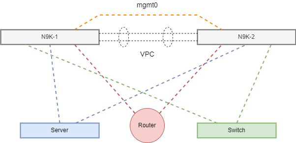
If your new to VPC or Virtual Port Channel this is a simple article that outlines the basic overall configuration along with some terms. A VPC or Virtual Port Channel is the ability to bond together multiple switches, so that they appear as a single switch from downstream hosts. Basically it creates a single control plane. This ability is also know as multi-chassis or in some cases MLAG. This feature is found on NX-OS based NEXUS switches. VPC is similar to VSS or Virtual Switch System found on Catalyst 4500s and 6500s family of switches. The key difference between VPC and VSS is that VSS creates a single logical switch much the same way FlexStack and StackWise to with physical external cables.
We need to start off by enabling VPC along with LACP in order to build a Virtual Port Channel between N9K-1 and N9K-2.
N9K-1#configure terminal
N9K-1(config)#feature vpc
N9K-1(config)#feature lacp
N9K-1(config)#feature vtp
Now lets simply enable the same features on N9K-2.
N9K-2#configure terminal
N9K-2(config)#feature vpc
N9K-2(config)#feature lacp
N9K-2(config)#feature vtp
We need a keepalive interface along with a vrf for the VPC domain. The Management interface is the perfect interface to run the keepalives over, and the management vrf in already in place.
N9K-1(config)#interface mgmt0
N9K-1(config-if)#ip address 10.0.0.1/30
N9K-1(config-if)#no shutdown
Lets move over to N9K-2, and configure the on side of the keepalive for the VPC domain.
N9K-2(config)#interface mgmt0
N9K-2(config-if)#ip address 10.0.0.2/30
N9K-2(config-if)#no shutdown
At this point we’re ready to configure the VPC domain. The basic requirements for the VPC domain is a keepalive interface for the control plan message exchange along with the Role Priority. The Role Priority can range from 1 to 65636 with the lower value more preferred when the election process occurs between the Switches. So I’m simply going to use a value of 1 and 2 for this example. I’m also going to be using a VPC domain value of 1 on both Switches.
N9K-1(config)#vpc domain 1
N9K-1(config-vpc-domain)#role priority 1
N9K-1(config-vpc-domain)#peer-keepalive destination 10.0.0.2 source 10.0.0.1 vrf management
N9K-1(config-vpc-domain)#exit
N9K-1(config)#
Lets do the same thing on N9K-2 with the exception of the priority value along with the source and destination for the keepalive. Role priority needs to have a less preferred or higher value, and we need to reverse the keepalive direction.
N9K-2(config)#vpc domain 1
N9K-2(config-vpc-domain)#role priority 2
N9K-2(config-vpc-domain)#peer-keepalive destination 10.0.0.1 source 10.0.0.2 vrf management
N9K-2(config-vpc-domain)#exit
N9K-2(config)#
Now we’re finally at the point where we can begin to build out the Peer Links which actually carry the VPC along with the Port Channel control plane information. This is the actual fabric or MLAG portion of the configuration depending on your point of view. It’s basically the backbone of the VPC where the rubber meets the road. I’m going to being using ethernet1/1 and ethernet1/2 in the following examples. I’m also going to be using Channel Group 200, but you could using anything you want. I would recommend using a higher value for the Peer Link if you plan on starting your Host Ports VPCs at 1. In a real world configuration at least two 40 Gig ports would be used for the Peer Link, but for this example I’m simply going to use ethernet1/1 and ethernet1/2.
N9K-1(config)#interface ethernet1/1-2
N9K-1(config-if)#description VPC Peer Link
N9K-1(config-if)#channel-group 200 mode active
N9K-1(config-if)#no shutdown
Now let jump over to N9K-2 and do the same thing.
N9K-2(config)#interface ethernet1/1-2
N9K-2(config-if)#description VPC Peer Link
N9K-2(config-if)#channel-group 200 mode active
N9K-2(config-if)#no shutdown
AT this point we are ready to build the Port Channel for the Peer Link. That’s right the Peer Link is a Port Channel with a special peer-link command which turns it into a Peer Link. We also need to make sure we configure it as a Trunk so it will be able to carry the 802.1q encapsulated traffic across the link. It’s also a really good idea to match the Peek Link and the Port Channel. You don’t have to do this, but it’s really good idea to keep them the same.!
N9K-1(config)#interface port-channel 200
N9K-1(config-if)#description VPC Peer Link
N9K-1(config-if)#switchport mode trunk
N9K-1(config-if)#vpc peer-link
N9K-1(config-if)#no shutdown
Lets do the same thing on N9K-2, making sure we don’t forget the Peer Link and Trunk configuration. Like with any channel group you move to the port channel itself to configure specific configurations.
N9K-2(config)#interface port-channel 200
N9K-2(config-if)#description VPC Peer-Link
N9K-2(config-if)#switchport mode trunk
N9K-2(config-if)#vpc peer-link
N9K-2(config-if)#no shutdown
Host Port Configurations
As with most configurations between Switches and Routers the need to encapsulate or trunk VLANs is usually a common task. The same holds true with Virtual Port Channels. We need to make sure and account for this when configuring port channels with regards to Routers and Switches. This of course is not the case when it comes to a downstream Server. In the following examples I’m not specifying any specific port or vpc numbers. I’m simply giving examples of the overall configurations.
Southbound Router or Switch configuration.
N9K-1(config)#interface ethernetx/y
N9K-1(config-if)#channel-group x mode active
N9K-1(config-if)#interface port-channel x
N9K-1(config-if)#switchport
N9K-1(config-if)#switchport mode trunk
N9K-2(config-if)#vpc x
N9K-1(config-if)#no shutdown
Southbound Router or Switch configuration.
N9K-2(config)#interface ethernetx/y
N9K-2(config-if)#channel-group x mode active
N9K-2(config-if)#interface port-channel x
N9K-2(config-if)#switchport
N9K-2(config-if)#switchport mode trunk
N9K-2(config-if)#vpc x
N9K-2(config-if)#no shutdown
The overall configuration for the Server host ports is basically the same with the exception of the 802.1q trunk configuration. This is not to say you couldn’t or shouldn’t trunk downstream to a Server is totally possible considering that 802.1q is an open standard. The bigger consideration on the Server side would be the NIC Teaming configuration which essentially enabled LACP. Remember both ends have to agree on running LACP between one another in order to form a successful Virtual Port Channel. If both ends are not configured correctly the Port Channel will not learn Layer 2 information. It will be the ports or port that learns Layer 2 information which is an indication that the configuration is incorrect.
Southbound Server configuration.
N9K-1(config)#interface ethernetx/y
N9K-1(config-if)#channel-group x mode active
N9K-1(config-if)#interface port-channel x
N9K-1(config-if)#switchport
N9K-2(config-if)#vpc x
N9K-1(config-if)#no shutdown
Southbound Server configuration.
N9K-2(config)#interface ethernetx/y
N9K-2(config-if)#channel-group x mode active
N9K-2(config-if)#interface port-channel x
N9K-2(config-if)#switchport
N9K-2(config-if)#vpc x
N9K-2(config-if)#no shutdown
I hope you found this post on NX-OS Virtual Port Channels helpful and informative. Be sure to let me know what you think by leaving suggestions, and feedback in the comments section below. You can find out more about these and other articles be checking out recent posts and archives. To learn more about me be sure to check out the About page. And as always thanks again for visiting The Packet.