
The most basic requirement of any OSPF design is that all areas in an Open Shortest Path First ( OSPF ) system must be physically connected to the backbone 0. In some cases, where this is not possible, you can use a Virtual Link to connect broken areas or none backbone areas to area 0. You can also use Virtual Links to connect two parts of a partitioned backbone through a non-backbone area. The area through which you configure the Virtual Link is commonly referred to as the transit area, which must have full routing information.
Virtual Link Features
- Virtual Links run as demand circuits
- Virtual Links are created between the transit area, and area 0
- Virtual Links point at the [ Router ID ] on each side of the transit area, and not an ip address
- Links can be either Physical or Virtual
- Virtual Links are basically a unicast connections between a broken areas and area 0
- GRE Tunnels can be used
- Used for form unicast multi-hop connections back to area 0
- Transit areas back to area 0 can’t be of type Stub
- Transit areas can’t have any filters such as ACL’s or distributed list
- Inherits cost from SPT between end points. The cost must be below 65535
Lets get started off with router R1 interfaces configurations, along with OSPF for area 0. All four routers will utilize their receptive loopback interfaces as their OSPF Router ID / Link ID, however I’m not going to be running the OSPF process on any of loopback interface because it’s simply not necessary for this example.
R1#configure terminal
R1(config)#interface ethernet0/0
R1(config-if)#ip address 10.1.2.1 255.255.255.252
R1(config-if)#interface loopback 0
R1(config-if)#ip address 1.1.1.1 255.255.255.255
R1(config-if)#router ospf 1
R1(config-router)#network 10.2.3.0 0.0.0.3 area 0
R1(config-router)#exit
R1#
Next lets do the same thing on router R4 and associate it’s interface with OSPF area 2.
R4#configure terminal
R4(config)#interface ethernet0/0
R4(config-if)#ip address 10.3.4.1 255.255.255.252
R4(config-if)#interface loopback 0
R4(config-if)#ip address 4.4.4.4 255.255.255.255
R4(config-if)#router ospf 1
R4(config-router)#network 10.3.4.0 0.0.0.3 area 2
R4(config-router)#exit
R4#
Unlike routers R1, and R4 router R2 will have an interface associated within area 0, and 1.
R2#configure terminal
R2(config)#interface ethernet0/0
R2(config-if)#ip address 10.1.2.2 255.255.255.252
R2(config-if)#interface ethernet0/1
R2(config-if)#ip address 10.2.3.2 255.255.255.252
R2(config-if)#interface loopback 0
R2(config-if)#ip address 2.2.2.2 255.255.255.255
R2(config-if)#router ospf 1
R2(config-router)#network 10.1.2.0 0.0.0.3 area 0
R2(config-router)#network 10.2.3.0 0.0.0.3 area 1
R2(config-router)#exit
R2(config)#
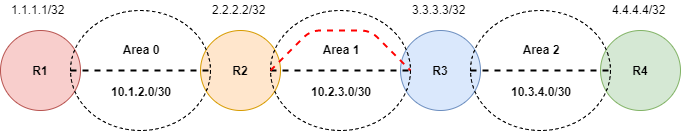
Similarly router R3 will have an interfaces associated with area 1, and 2. In this example area 2 will be a broken area unable to reach area 0, and area 1 will be the transit area between 0 and 2.
R3#configure terminal
R3(config)#interface ethernet0/0
R3(config-if)#ip address 10.2.3.2 255.255.255.252
R3(config-if)#interface ethernet0/1
R3(config-if)#ip address 10.3.4.1 255.255.255.252
R3(config-if)#interface loopback 0
R3(config-if)#ip address 3.3.3.3 255.255.255.255
R3(config-if)#router ospf 1
R3(config-router)#network 10.2.3.0 0.0.0.3 area 1
R3(config-router)#network 10.3.4.0 0.0.0.3 area 2
R3(config-router)#exit
R3(config)#
At this point we have valid OSPF connectivity between area 0, and area 1, however area 2 is currently a broken area due to the fact that its not directly connected to the backbone area 0. It’s essentially a stranded area that can’t reach area 0 to exchange OSPF hellos, and LSA. This is were Virtual Links come into play. We can use a transit area in this case area 1 to repair the broken link state between area 0, and 2 by building a Virtual Link. Lets get started with router R2 by building a Virtual Link using router R3 OSPF database Link ID 3.3.3.3.
R2(config)#router ospf 1
R2(config-router)#area 1 virtual-link 3.3.3.3
R2(config-router)#end
R2#
Now lets build the other end of the Virtual Link on router R3 using R2 OSPF database Link ID 2.2.2.2.
R3(config)#router ospf 1
R3(config-router)#area 1 virtual-link 2.2.2.2
R3(config-router)#end
R3#
At his point we should see the Virtual Link come up between router R2 and R3.
R3#OSPF-5-ADJCHG: Process 1, Nbr 3.3.3.3 on OSPF_VL12 from LOADING to FULL, Loading Done
We can see from the above output that the Virtual Link demand circuit between router R2, and R3 has come up with a full adjacency, along with the exchange of LSAs which means that area 2 is no longer broken.
I hope you found this post on OSFP Virtual Links helpful and informative. Be sure to let me know what you think by leaving suggestions, and feedback in the comments section below. You can find out more about these and other articles be checking out recent posts and archives. To learn more about me be sure to check out the About page. And as always thanks again for visiting The Packet.