
Layer 2 Tunnel Protocol Version 3
It’s a standards based Layer 2 VPN / IP based protocol governed by the IETF ( RFC 3931 ) working group current version 3 as the name implies. Basically it allows you to extend ( stretching ) your LAN across the WAN much in the same way OTV, and VPLS does. You can have multiple virtual circuits per interfaces which allows for greater scale, and flexibility. If you we’re to run a packet capture on the control plane you would see that L2TPv3 has it’s own Layer 4 protocol 115.
Supported Layer 2 Encapsulated Payloads
- Frame Relay
- Ethernet
- 802.1q VLAN Tagging
- IEEE 802.1QinQ and QinAny VLAN
- HDLC
- PPP
- ATM
- RFC – 3931
Requirements
- Cisco Express Forwarding or CEF must be enabled
- The source of the L2TPv3 tunnel should originate from a loopback interface
- The destination of the L2TPv3 tunnel should terminate on a loopback
- The loopback interfaces must have unicast reachability
- Optional if not already enabled would be to turn on CDP
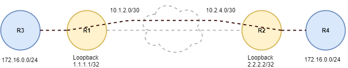
Lets start off by configuring the Serial WAN interface connections between Routers R1, and R2.
R1#configure terminal
R1(config)#interface Serial0/0
R1(config-if)#ip address 10.1.2.1 255.255.255.252
R1(config-if)#exit
R1(config)#
Lets do the same on Router R2.
R2#configure terminal
R2(config)#interface Serial0/0
R2(config-if)#ip address 10.1.2.2 255.255.255.252
R2(config-if)#exit
R2(conffig)#
The next thing we need to do is bring up the loopback interfaces on router R1, and R2 for L2TPv3 tunnel termination. This where we are going to source the L2TPv3 traffic from. In most cases you would want to run a dynamic routing protocol on the control plane between routers R1, and R2, but for simplicity I’m going to create a couple of static routes between R1, and R2 to reach their respective loopback interfaces.
R1(config)#interface loopback0
R1(config-if)#ip address 1.1.1.1 255.255.255.255
R1(config-if)#exit
R1(config)#ip route 2.2.2.2 255.255.255.255 10.1.2.2
R1(config)#
Now lets do the same thing on Router R2.
R2(config)#interface loopback0
R2(config-if)#ip address 2.2.2.2 255.255.255.255
R2(config-if)#exit
R2(config)#ip route 1.1.1.1 255.255.255.255 10.1.2.1
R2(config)#
At this point we have basic Layer 2 / Layer 3 WAN connectivity between Routers R1, and R2. Since Routers R1, and R2 will serve as the actual beginning and end of the L2TPv3 tunnel control plane we can begin the Pseudo Wire Class configuration. You can use whatever name you want for the Pseudo Wire Class I’m going to keep it simple and clean and use L2TPv3 on both sides of the tunnel.
R1(config)#pseudowire-class L2TPv3
R1(config-pw-class)#encapsulation l2tpv3
R1(config-pw-class)#ip local interface loopback0
R1(config-pw-class)#exit
R1(config)#
Now lets create the the same Pseudo Wire Class configuration on Router R2.
R2(config)#pseudowire-class L2TPv3
R2(config-pw-class)#encapsulation l2tpv3
R2(config-pw-class)#ip local interface loopback0
R2(config-pw-class)#exit
R2(config)#
This is where things start to get a little strange. We don’t want to assign an actual Layer 3 address to LAN interface of router R1. Instead we want to source the loopback address we configured earlier, and bind the Pseudo Wire Class. We can accomplish this using the xconnect command.
R1(config)#interface fastEthernet0/0
R1(config-if)#no shutdown
R1(config-if)#xconnect 2.2.2.2 1 encapsulation l2tpv3 pw-class L2TPv3
R1(config-if)#end
R1#
Now lets that do the same thing on router R2.
R2(config)#interface fastEthernet0/0
R2(config-if)#no shutdown
R2(config-if)#xconnect 1.1.1.1 1 encapsulation l2tpv3 pw-class L2TPv3
R2(config-if)#end
R2#
Last, but not least lets bring up the LAN ( 172.16.0.0/24 ) interface on router R3, and R4.
R3#configure terminal
R3(config)#interface fastEthernet0/0
R3(config-if)#ip address 172.16.0.3 255.255.255.0
R3(config-if)#end
R3#
Now lets do the same thing on router R4.
R4#configure terminal
R4(config)#interface fastEthernet0/0
R4(config-if)#ip address 172.16.0.4 255.255.255.0
R4(config-if)#end
R4#
At this point we should have full Layer 2 reachability between router R3, and R4.
R3#ping 172.16.0.3 source fastethernet0/0 repeat 20
Type escape sequence to abort.
Sending 5, 100-byte ICMP Echos to 172.16.0.4, timeout is 2 seconds:
Packet sent with a source address of 172.16.0.3
!!!!!!!!!!!!!!!!!!!!
Success rate is 100 percent (5/5), round-trip min/avg/max = 68/92/108 ms
R3#
Now lets check to make sure we have full unicast ICMP reachability from router R4.
R4#ping 172.16.0.4 source fastethernet0/0 repeat 20
Type escape sequence to abort.
Sending 20, 100-byte ICMP Echos to 172.16.0.4, timeout is 2 seconds:
Packet sent with a source address of 172.16.0.4
!!!!!!!!!!!!!!!!!!!!
Success rate is 100 percent (20/20), round-trip min/avg/max = 68/92/108 ms
R4#
I hope you found this post on L2TPv3 helpful and informative. Be sure to let me know what you think by leaving suggestions, and feedback in the comments section below. You can find out more about these and other articles be checking out recent posts and archives. To learn more about me be sure to check out the About page. And as always thanks again for visiting The Packet.